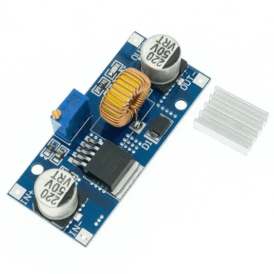
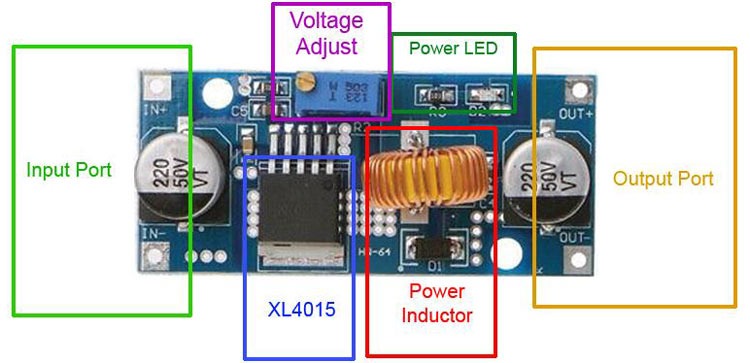
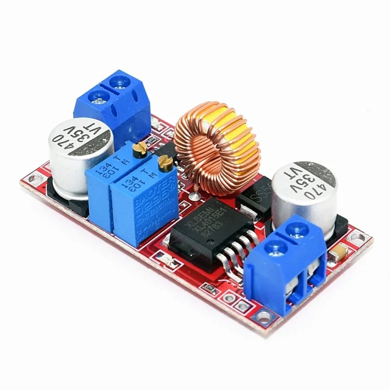
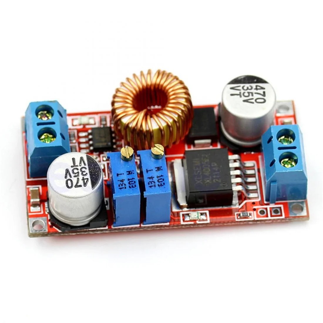
DC-DC CONVERTERS
Multi Output Voltage DC-DC 12V to 3.3V 5V 12V Power Module
In stock
Features :
- Output power on/off switch
- Two-row multiple pin outputs, easy to use and connect
- Red LED illuminates when input DC power is supplied and output is turned ON.
- Outputs
- 3.3V DC at 800mA maximum current
- 5.0V DC at 800mA maximum current
- 12V DC (the 12V output is directly connected to the input, i.e. with 12VDC input, this output will be 12VDC; with 9VDC input, this output will be 9VDC)
- Small and Handy Module.
- Dual-side plate design
- Easy to use.
sx1308 dc – dc module
In stock
Features:
- Oscillation frequency 1.2MHz
- efficiency is as high as 95%
- The circuit has short circuit protection, overheating protection function
- 10k to adjust potentiometer, adjust the output voltage
TB6612 BLUE
In stock
Power Pins
- Vmotor – This is the voltage for the motors, not for the logic level. Keep this voltage between 4.5V and 13.5V. This power supply will get noisy so if you have a system with analog readings or RF other noise-sensitive parts, you may need to keep the power supplies seperate (or filtered!)
- Vcc – this is the voltage for the logic levels. Set to the voltage logic you’ll be using on your microcontroller. E.g. for Arduinos, 5V is probably what you want. Can be 2.7V to 5.5V so good for 3V or 5V logic
- GND – This is the shared logic and motor ground. All grounds are connected
Signal in Pins
These are all ‘Vcc logic level’ inputs
- INA1, INA2 – these are the two inputs to the Motor A H-bridges
- PWMA – this is the PWM input for the Motor A H-bridges, if you dont need PWM control, connect this to logic high.
- INB1, INB2 – these are the two inputs to the Motor B H-bridges
- PWMB – this is the PWM input for the Motor B H-bridges, if you dont need PWM control, connect this to logic high.
- STBY – this is the standby pin for quickly disabling both motors, pulled up to Vcc thru a 10K resistor. Connect to ground to disable.
Motor Out Pins
These are ‘Vmotor level’ power outputs
- Motor A – these are the two outputs for motor A, controlled by INA1, INA2 and PWMA
- Motor B – these are the two outputs for motor B, controlled by INB1, INB2 and PWMB
TB6612 RED
In stock
Features :
- Output current: Iout=1.2A(average) / 3.2A (peak)
- Standby control to save power
- CW/CCW/short break/stop motor control modes
- Built-in thermal shutdown circuit and a low voltage detecting circuit
- All pins of the TB6612FNG broken out to 0.1″ spaced pins
- Filtering capacitors on both supply lines
TCA9548A I2C MUX MODULE
In stock
Specification and Features :
- 1-to-8 Bidirectional Translating Switches.
- Supports Hot Insertion.
- Low Standby Current.
- 1-to-8 Bidirectional Translating Switches.
- Active-Low Reset Input.
- Power Up With All Switch Channels Deselected.
- I2C Bus and SMBus Compatible.
- 5-V Tolerant Inputs.
- Latch-Up Performance Exceeds 100 mA Per JESD 78, Class II.
Pin Description :
Power Pins:
- Vin – this is the power pin. Since the sensor chip uses 3-5 VDC. To power, the board, give it the same power as the logic level of your microcontroller – e.g. for a 5V micro like Arduino, use 5V.
- GND – common ground for power and logic.
I2C Control-Side pins :
- SCL – this is the I2C clock pin for the chip itself, connect to your microcontrollers I2C clock line.
- SDA – this is the I2C data pin for the chip itself, connect to your microcontrollers I2C data line.
- RST – this is the reset pin, for resetting the multiplexer chip. Pulled high by default, connect to ground to reset
- A0 A1 A2 – these are the address selection pins for the multiplexer. By default, the multiplexer is at address 0x70 and these three pins are pulled low. Connect them to Vin to set the address to 0x71 – 0x77.
- A0 is the lowest-significant bit (if it is pulled high, it will increase the address by 1).
- A1 is the 2nd-lowest-significant bit (if it is pulled high, it will increase the address by 2).
- A2 is the 3rd-lowest-significant bit (if it is pulled high, it will increase the address by 4).
I2C Multiplexed-Side pins:
- SDx and SCx: There are 8 sets of SDx and SCx pins, from SD0/SC0 to SD7/SC7. These are the multiplexed pins. Each one is a completely separate I2C bus set. So you have 8 I2C devices with identical addresses, as long as they are on one I2C bus each.
- These pins do not have any pullups installed, so if you are using a chip or breakout without I2C pull-ups be sure to add them! Nicely, you can have Vin be 3.3V and have these pins pulled up to 5V (that is, they are 5V compliant).
Program :
We suggest using this little helper to help you select the port
#define TCAADDR 0x70
void tcaselect(uint8_t i) {
if (i > 7) return;
Wire.beginTransmission(TCAADDR);
Wire.write(1 << i);
Wire.endTransmission();
}
You can then call tcaselect(0) thru tcaselect(7) to set up the multiplexer.
Note that you if you happen to have I2C devices with I2C address 0x70, you will need to short one of the Addr pins on the TCA9548 breakout to Vin in order to make it not conflict. Given that you can have 0x70 thru 0x77, just find one that’s free and you’re good to go.
Note : Product may vary in two variants TCA9548A & PCA9548A
Tp4056 Module – Type C
In stock
Features:
- Ampere meter can only be connected to a 5v input end of the module.
- It is better than the charging current is 37% of the battery capacity. If you charge the battery of 1000mAh, a current of 400mAh is enough.
- The connection wire should not be too thick.
- Make sure the connect point is good.
- If the input voltage is too high, like 5.2v, the current will be less than 1000mA, it is normal. It is protection function, auto-subtract the charging current to avoid burn damage to the chip.
- NO Reverse polarity.
Xl4015 Module
In stock
Features :
- High efficiency up to 96%
- The built-in thermal shutdown function
- Built-in current limit function
- In-Built output short protection function
- Input reverse polarity protection: None (if required, the high current diode in series with the input).
XL4015 MODULE CCCV
In stock
Features
- Short circuit protection: Yes(limited current 8A)
- Over-temperature protection: Yes (automatically turn off the output after over temperature)
- Input reverse connection protection: None, (If necessary, please input a large current diode in the input string)
- Installation method: 4 3mm silk
- Wiring method: terminal block or soldering terminal,
- V-IN is input.
Applications:
- LCD Monitor and LCD TV
- Portable instrument power supply
- Telecom / Networking Equipment
XL6009 DC-DC
In stock
Features :
- The performance is much higher than LM2577.
- Non-isolated Boost converter.
- It has a non-synchronous rectifier.
- Small and Handy voltage regulator module.
XL6009 DC-DC with Display
In stock
XL6009 is a 4A switch current high performance boost ( BOOST ) module. This module uses the second-generation high-frequency switching technology XL6009E1 as the core chip, and its performance far exceeds that of the first-generation technology LM2577 . The XL6009 booster module has lower cost and better performance, and the LM2577 module is about to be eliminated.